
Design
Mechanism
We designed to turn fluorescence on and off using a strand displacement reaction on DNAo.
Because of DNAo has a simple two-dimensional structure, we create a rectangle plate made of DNA origami. First, single-strand DNA (ssDNA) A with fluorescent molecules attached is fixed on a DNAo plate. In this state, the fluorescent molecule is turned on, and the fluorescent substance emits light (Fig. 1a). After that, by adding ssDNA B with a quencher molecule, DNA B hybridizes with DNA A on origami to form double-strand DNA (dsDNA) A-B. At this time, the fluorescent molecule and the quencher molecule approach each other, the fluorescence disappears and turns OFF (Fig. 1b). Finally, DNA B with a quencher molecule is peel away from dsDNA A-B by DNA Releaser, returning to the initial state (Fig. 1a).
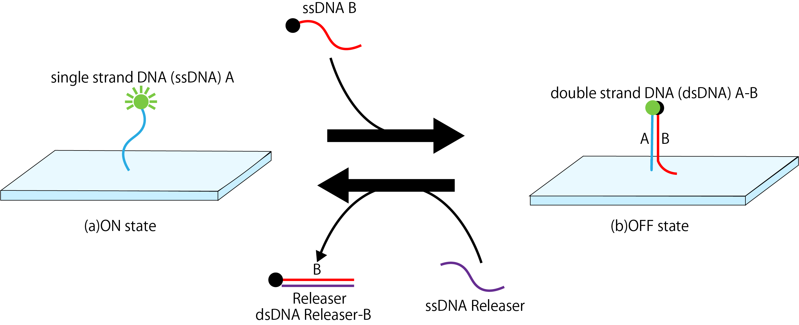
Figure1: Mechanism
DNA strand displacement reaction
We added some functions to DNAo using strand displacement reaction. These functions are as follows.
- A function to combine quencher molecule and a fluorescent molecule.
- A function to dissociate the quencher molecule and the fluorescent molecule after binding, and return the fluorescent molecule to the state where it can bind to the quencher molecule again.
Fig. 2 shows a reaction path scheme to achieve a system that provides these functions. First, the fluorescent molecule modified A strand that exists in DNAo is bind to the quencher molecules modified B strand. At the same time, the DNA strands of Input and Template which is the bottom part of Gate1 is also bound. Along with the strand displacement reaction, the releaser strand originally bound to Gate1 is released. When the released releaser strand binds to B, A returns to a single strand again. By following this series of flows, the functions that we want to add can be achieved.
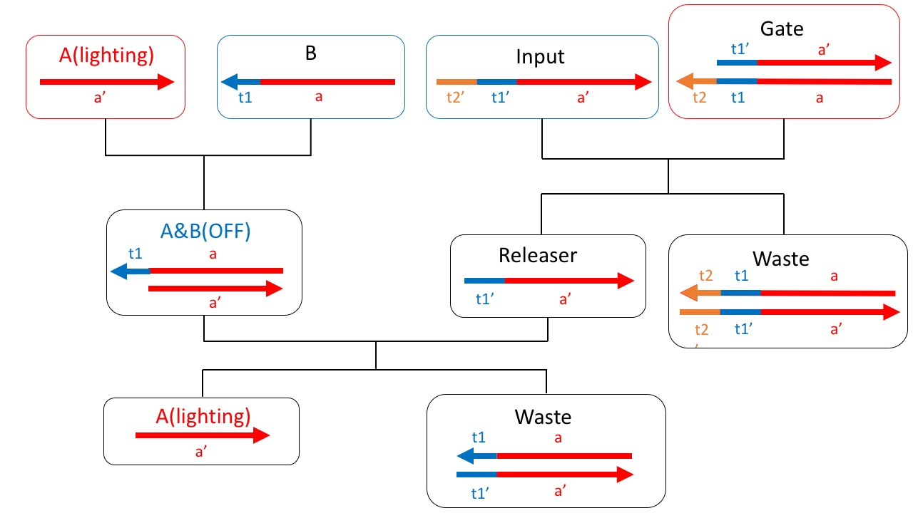
Figure2: The scheme about this project
However, in this state, Input and B become complementary, causing unwanted reactions. Therefore, using mismatched base pairs, a sequence was designed so that B and Input do not bind. Fig.3 is a redesigned scheme using mismatched base pairs.
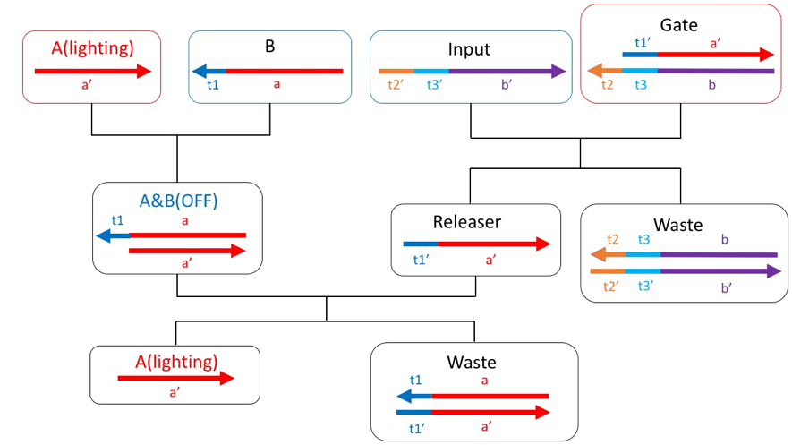
Figure3: Redesigned the scheme
Reaction pathway of DNA circuit
First, A and Gate are prepared as initial concentrations, and the reaction of the scheme starts when B and Input are inserted. The overall scheme reaction is divided into three reactions. Reaction1 and Reaction2 start reaction as soon as B and Input are inserted, and proceed to Reaction3 when these two reactions occurred.
Reaction1
Double strands are generated by the high end of the initial A and the input B. At this time, FRET occurs when the fluorescent molecule modified with A and B approaches the quenching molecule, and the fluorescence is absorbed, and A is turned off.
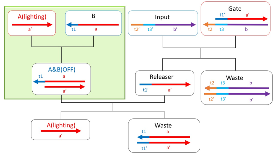
Figure4: Reaction part of reaction1
Figure5: Video of reaction1
Reaction2
The gate and input at the initial concentration undergo a strand displacement reaction from toe hold t2, and the releaser is discharged fromthe gate. This reaction starts simultaneously with Reaction1.
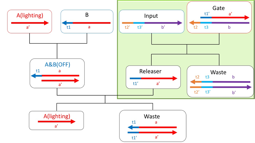
Figure6: Reaction part of reaction2
Figure7: Video of Reaction2
Reaction3
The double-stranded A & B generated by Reaction1 and the Releaser discharged by Reaction2 cause a strand displacement reaction from toe hold t1, and A is discharged. Since the discharged A is separated from the quenching molecule, it emits fluorescence again and becomes ON.
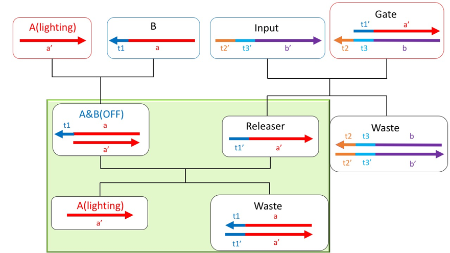
Figure8: Reaction part of reaction3
Figure9: Video of reaction3
DNA origami
The following design is required to add functions to DNAo.
・ Design to place ssDNA on the DNAo
To describe this arrangement, we will refer to DNA origami about size, shape, and control interval of ssDNA arrangement.
For DNA origami, we used highly reliable DNA origami used in many papers [1][2]. In addition, M13 (7249 bases) was used for Scaffold, and DNA with a partial alias of 32 bases was used for Staple. The entire sequence of Staple is shown in supplement information.
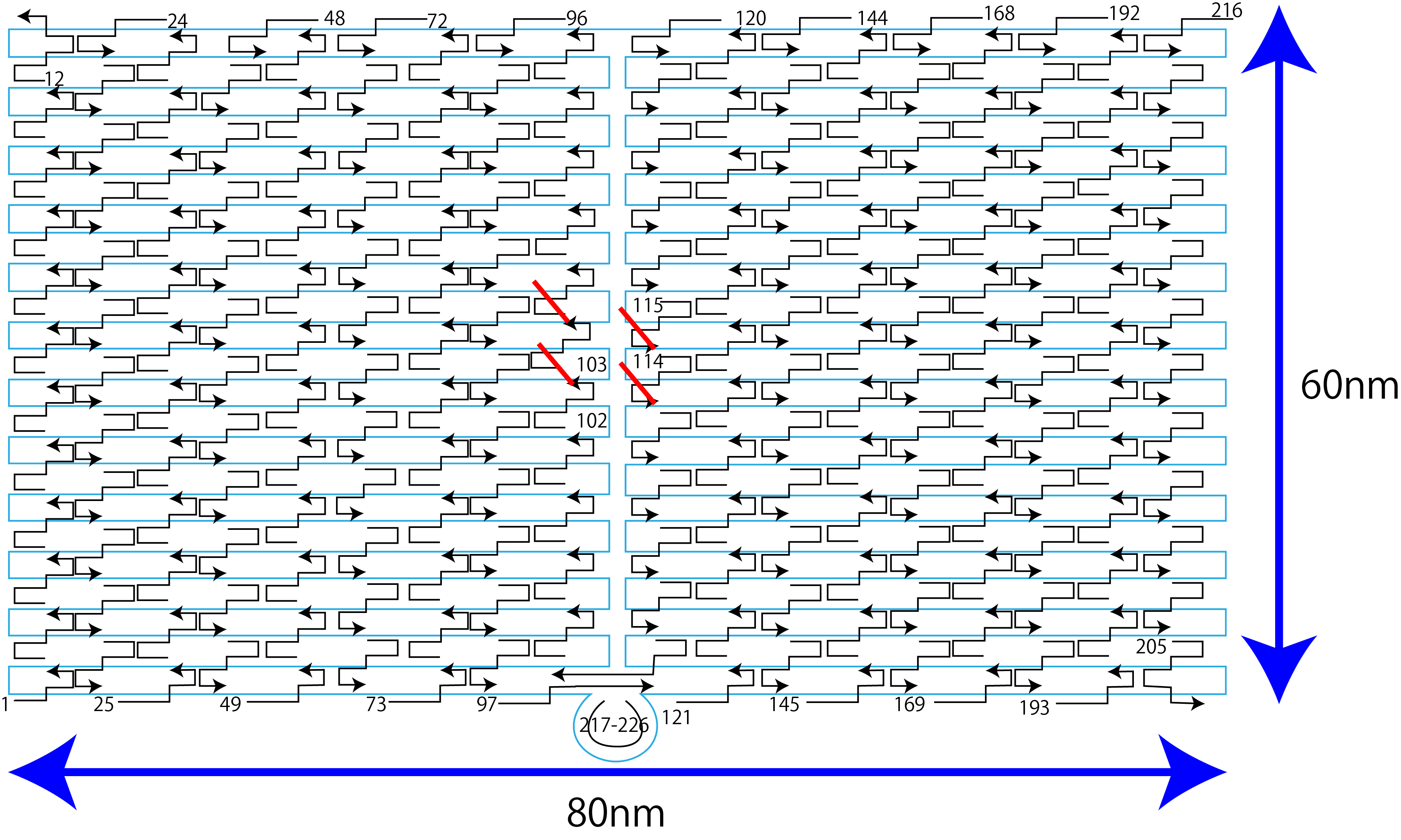
Figure10: DNA origami
The size of this DNAo is a rectangle with a width of about 110 nm and a length of about 70 nm. Staples for weaving scaffolds are arranged at intervals of 5~10 nm in width and 5~10 nm in length, and ssDNA can be placed on the DNAo plate by extending the sequence of this staple. Therefore, the control interval of ssDNA arrangement is 5~10 nm. This time, the four staples are extended to place on the DNAo. The reason for extending four staples instead of one was that one could not clearly obtain the difference between fluorescence and quenching. The reason why only a part of origami is used for the number of fluorescent light is that a relatively large DNA origami was used this time in order to make the conditions the same as our application (image element etc.). Fig. 11 shows the sequence after extension.
name Sequence
102 AGACAGTCATTCAAAAGGGTGAGAAGCTATAT TTT GGAGTGATGTGATGGGATGGTGATG
103 TTTCATTTGGTCAATAACCTGTTTATATCGCG TTT GGAGTGATGTGATGGGATGGTGATG
114 ATCGGCTGCGAGCATGTAGAAACCTATCATAT TTT GGAGTGATGTGATGGGATGGTGATG
115 CCTAATTTACGCTAACGAGCGTCTAATCAATA TTT GGAGTGATGTGATGGGATGGTGATG
Figure11: Extended DNA sequence: The colored base is the extension site and the red base is the hybridization domain. The green base has a margin between the DNAo and the extended base.