
Simulation
Simulation of DNA strand displacement reaction by nupack
In this project, we assumed that the reaction starts by injecting B and Input into the initial state of A (and DNAo that binds to A) and Gate. Therefore, in order for the reaction shown in Design-Fig. 2 is achieved, the conditions below must be required.
- The Gate part is firmly bind in the initial state.
- Input does not combine with any strand other than Gate.
Each base sequence was set as follows to meet above conditions. After that, a research is performed for each condition to confirm these conditions are achieved.
A:GAGTGATGTGATGGGATGGTGATG
B:CATCACCATCCCATCACATCACTCCTCAAC
Input:GAGTAGTTAAGAAGTAATATGATAGAATAGTAATG
Releaser(Gate top strand):GTTGAGGAGTGATGTGATGGGATGGTGATG
Template(Gate bottom strand):CATTACTATTCTATCATATTACTTCTTAACTACTC
Regarding (1)
As described in Design, Releaser and Template are independent, and the reaction will not proceed normally unless a mismatch base pair is introduced. The introduction part of this mismatch base pair is shown in Fig. 1.
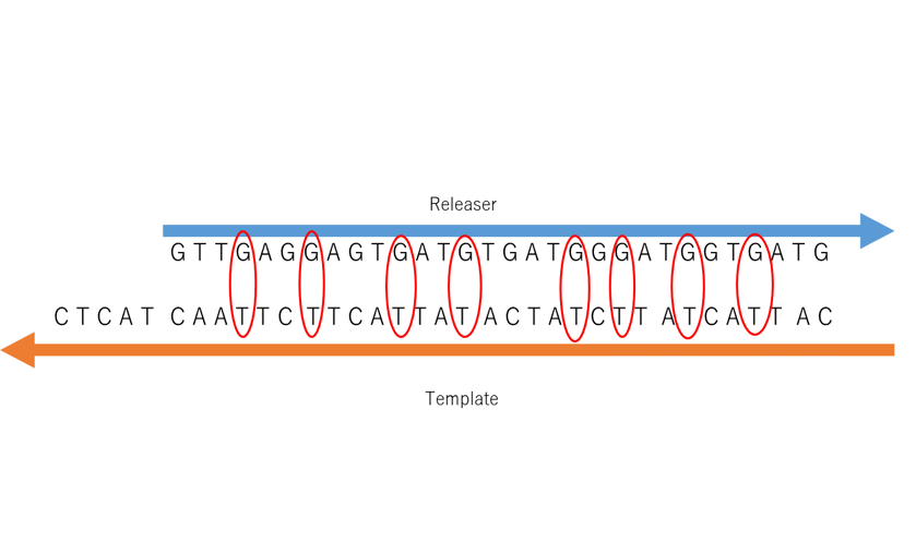
Figure1: The introduction of mismatch base pair. The enclosed part is mismatched base pair
Nupack is used to confirm whether the Releaser strand and Template strand react when the mismatched base pairs are simultaneously added to the both of the Releaser strand and Template strand. If reaction happens and a Gate strand is generated, a lot of Template-Releaser strands will be appeared. Fig. 2 shows the both of the hypothesis mentioned and the Nupack simulation result. From this figure, it can be seen that 1 μM of a double strand (Template-Releaser) is generated based on the Template and Releaser. A small amount of the strand appears at the bottom, which is different from the intended purpose as the amount of concentration is too small. Therefore, it can be said that the gate can be generated.
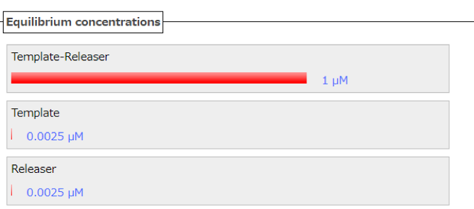
Figure2: the concentration of initial state(Releaser=1[μM]、Template=1[μM])
Regarding (2)
Input strand is inserted respectively to the A strand and B strand, then is confirmed whether both of the double strands are not combined. The Nupack data result is shown in Fig. 3 and 4. Based on Fig. 3, a combination of A strand and Input strand is not generated, shows that no double strand is formed even though both of the strands is mixed together. In addition, based on Fig. 4, the production of a double strand of B strand and Input is slightly can be seen but it does not affect the experiment as the concentration is too lower. In other words, it can be seen that B-Input combining is almost not performed.
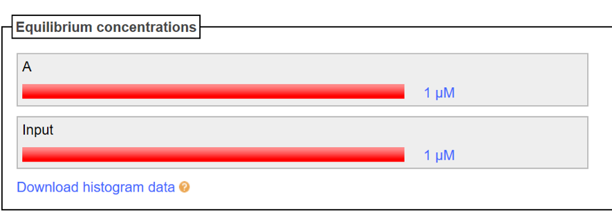
Figure3: A and Input(A=1[μM]、Input=1[μM])
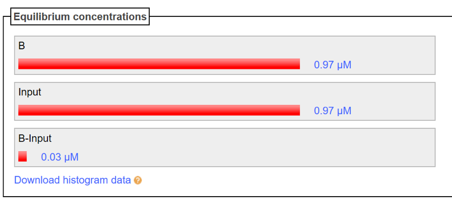
Figure4: B and Input(B=1[μM]、Input=1[μM])
Since both (1) and (2) are achieved, it can be said that there is a low possibility of an unintended reaction in this experiment.
used by Nupack URL http://www.nupack.org/partition/new
Simulation of DNA origami by caDNAno
※This time, considering the time required for the experiment, the DNA origami designed by us could not be used in the experiment. However, since we originally planned to use the DNA origami we simulated, we listed here as the simulation results.
For the simulation of DNA origami, based on the figure in Design section, the plan is designed by using caDNAno and the result is output to CanDo. The design is based on the M13(7249) used in the experiment with 20 helices and a helix length of 332 bases. The transfer part of the scaffold and staples are placed in appropriate positions. The design is shown in Fig. 5.
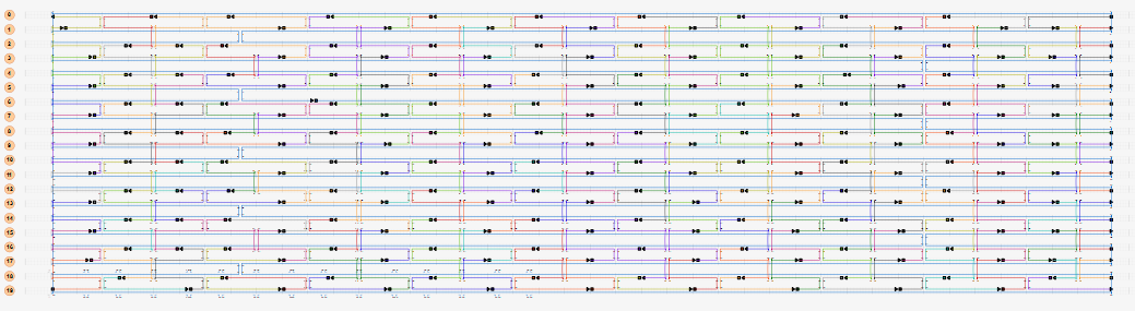
Figure5:caDNAno output
The results of outputting the design designed by caDNAno to CanDo are shown in Fig. 6 and 7. It shows that it becomes unstable as it turns red, and that it becomes stable as it turns blue. The validity of the design of DNA origami is confirmed.
Figure6:CanDo output
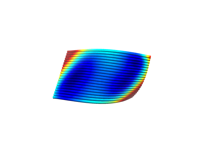
Figure7:CanDo output
The following supplementary information about simulation of other angle of DNAo.